These factors are inside heat transfer coefficient thermal contact resistance between the fin and the tube and outside heat transfer coefficient. Unique interlaced circuiting options assure uniform refrigerant distribution over the entire face area of the coil.
Understanding Coil Circuiting With A Simple Guide Campbell Sevey
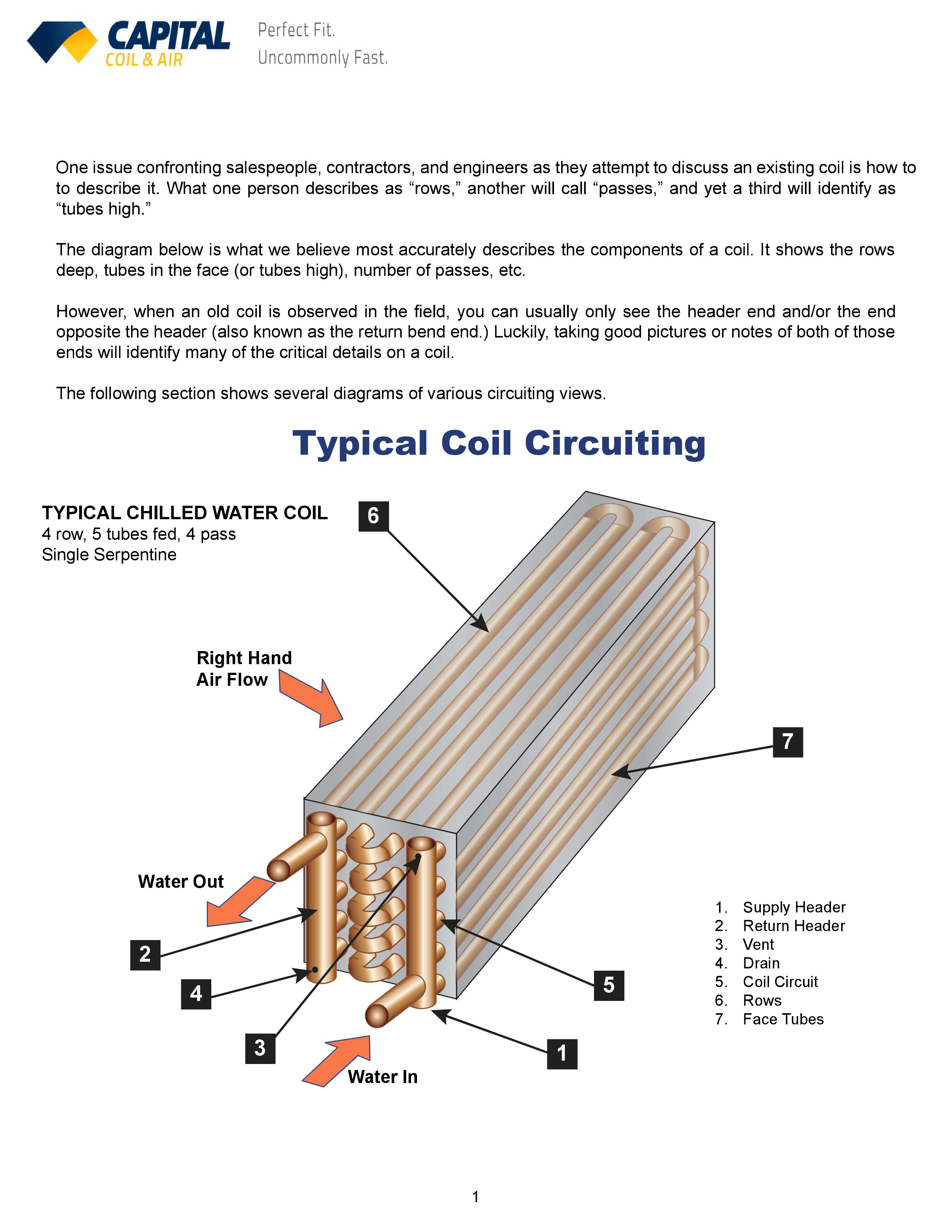
Coil geometry fins rows height length etc conditions of the air entering the coil cfm dbt wbt given the number of permutations of coil selections coil manufacturers often provide software tools like traneselect assist or topss.
. Durable Fully-Insulated Cabinet Our CVPVA aluminum V-coil is housed in a durable 24-gauge pre-painted taupe metallic cabinet. Four-Circuit Face Split Intertwined. Feeding 1 tube you will be making 192 passes through the coil which will essentially require a pump the size of your car to make that process work.
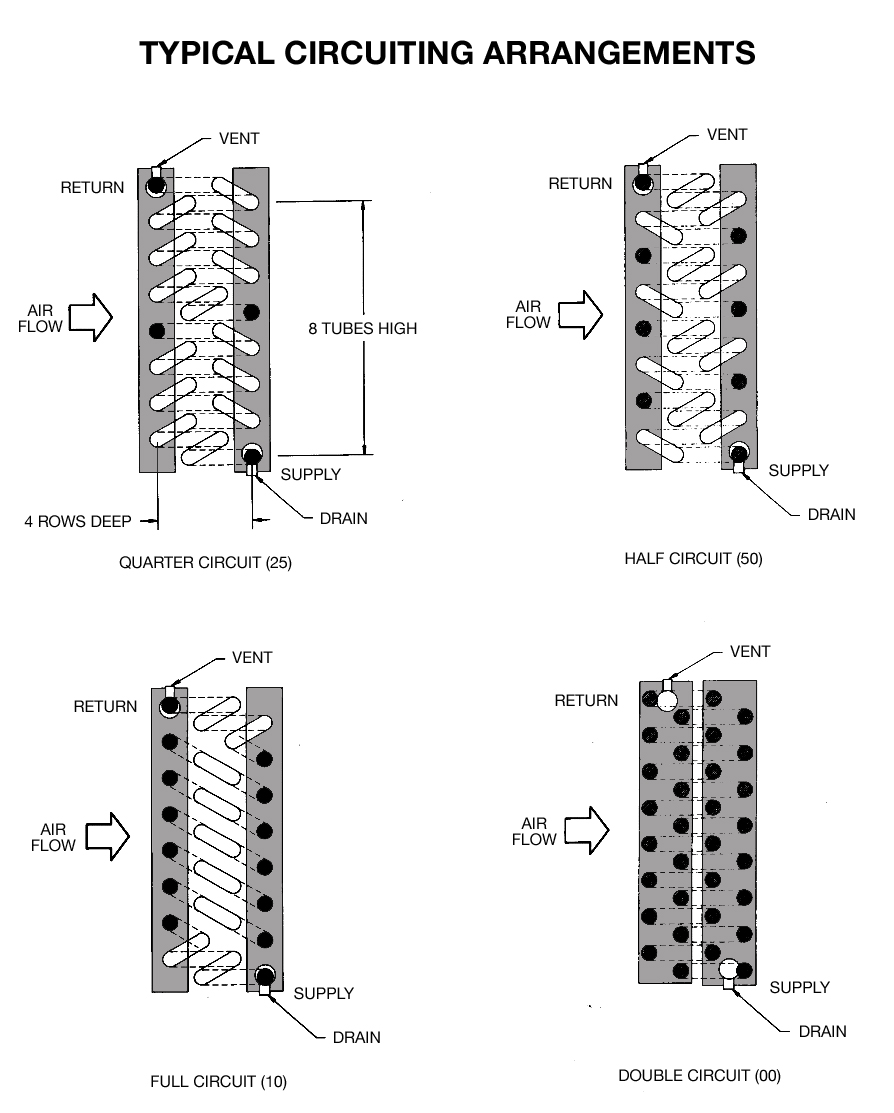
To avoid this evaporator coils come with distributors. Is called a maximum or full circuit coil s ee Figure 3. This differential is created and maintained compressor and performs several important functions.
An attempt is made to investigate the possibility of improving the coil. In both methods the cooling coil is treated as a single. Evaporator refrigerant circuit in the passage that exists between the inlet and outlet of the evaporator.
Combined these design changes allow for the same or better SEER ratings without growing the size of the coil. Custom design for new applications Matches existing dimensions and performance for existing coils. Ad Vetted Trusted Expert AC HVAC Furnace Pros.
Feeding 4 tubes See above. To refrigerant mass flow through the evaporator pressure drop must be created between the inlet and outlet ports. The evaporator curves are plotted as capacity tons versus sst and are based on two fixed factors.
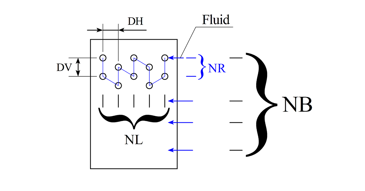
Low Price Guarantee Schedule Now. Fig 1 Evaporator Configuration Coil construction parameters Outside tube diameter do 1341 mm Inside tube diameter di 1209 mm Longitudinal tube spacing SL 2616 mm Transverse tube spacing ST 3175 mm 1 T 17KJKg 14 1420184 1076 0092 Ts1 1423 Tdpoint15 14 1420184 2076 No. The efficient thermal design of the cooling coil leads to a.
However this will increases the pressure drop in the refrigerant side and performances of the coil and system are adversely affected. The left circuit view can start with a low tube 0 or a high tube 1. Feeding 2 tubes equates to 96 passes and your pressure drop will still be enormous.
Four-Circuit Face Split Intertwined. It is configured in a V shape with the header tubes positioned at the top. Design of Evaporator with CO2 Coolant Bruce Nelson President Colmac Coil The selection process of the evaporators that operate in a system of refrigeration with CO2 is very similar to the selection of evaporators for ammonia.
These orifices are largest at the. Refrigerant-Refrigerant inlet refrigerant flow rate. Designing the suction line to be 1-38 yields suction line velocities of 1140 fpm and 2280 fpm at first and second stage which works great.
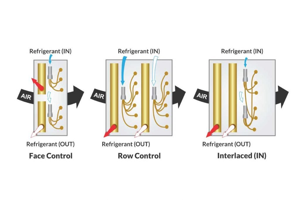
Select to start designing a circuit. Interlaced face control utilizes four distributors and four suction connections. Vertex Coil DesignTechnology Our new coil is constructed of flat aluminum refrigerant channels brazed to ridged aluminum fins.
Select again to end the circuit path. In the design of evaporator coils increasing refrigerant mass velocity can enhance the heat transfer of an evaporator coil. This option is most commonly used in multi-zone and VAV units.
Evaporator Coils For applications including comfort and process cooling dehumidification energy reclamation and more All sizes shapes capacities circuit patterns and fintube configurations Duplication of obsolete coils. Its made of steel or copper for better heat conduction and is often surrounded by fins that assist in both protection and dissipation of heat. ProConnect Guarantee Professional Background Checked Pros Upfront Transparent Pricing.
Air Second Side Evaporator Coil Design Calculation. We recommend designing your suction line velocity to be at least 1000 fpm or above for suction risers to ensure oil return to the compressor. Feeding 3 tubes 64 passes which is still too many.
The V configuration reduces coil resistance and enhances heat transfer. Of finsm Nf 554. This is used instead of a hand designation.
The distributor is ideally mounted pointing up or down to minimize this liquidgas separation it blends these two fluids and evenly distributes this stream to the individual coil circuits. HEATCRAFT EVAPORATOR COILS Single dual or quad compressor circuits allow precise capacity control. The construction is slightly different in that instead of having a distributor that properly distributes refrigerant to all the coils circuits a liquid overfeed coil has a supply header with an orifice welded into each tap tube.
A loop of suitable pipe containing the refrigerant and lubricant is put in direct contact with the ground or water body. Evaporator more liquid than can be completely boiled off through the coil. Wide fin spacing availability reduces the affect of frost build up on low temperature applications.
Focuses on Methods to design the cooling and dehumidifying coil or Direct Expansion evaporator coil. The coil retains up to 70 of the design capacity when one circuit is deactivated because the entire fin surface provides cooling keeping suction pressure high and allowing compressors to operate more efficiently. DX ground-coupled HPs use refrigerant in DX flooded or recirculation evaporator circuits for the ground pipe coils.
If the DX coil is a single-circuit coil and the system. The coil retains up to 70 of the design capacity when one circuit is deactivated because the entire fin surface provides cooling keeping suction pressure high and allowing compressors to operate more efficiently. Evaporator coil are usually based on log mean enthalpy or log equivalent dry-bulb temperature difference 1.
Thus a typical coil of 175 inch 044 m height. And efficient evaporator coils. Direct Expansion Evaporator An Evaporator or Direct Expansion DX Coil works on the refrigeration effect cooling occurs when a fluid under.
The evaporator coil is part of the air handler. 2 Figure 1 - Evaporator Coils EN NORMAL Rows 2345 681012 EF FACE CONTROL Rows 2345 681012 ER ROW CONTROL 6 Row EK. Calculated circuits number when inputEvaporator widthsingle tube length.
RESHAPING THE FUTURE OF HVAC Available Q4 2022 Thermostatic Expansion Valve. Which are usually based on log mean enthalpy or log equivalent dry-bulb temperature difference. This option is most commonly used in multi-zone and VAV units.
For applications that require face control and interlaced circuits we offer evaporator model EK. To maintain the same proportion of liquidgas as the stream travels from the distributor to coil. A RANGE OF COMFORT.
See Figure 1 - Evaporator Coils. Abstract Major factors affecting heat transfer between the refrigerant and air in a plate finned-tube heat exchanger otherwise known as an evaporator or condenser coil are discussed. It may be located in a dedicated air handler or might also be built into your furnace if the furnace is pulling double-duty as an air handler for the AC.
Create a new tube pattern after entering criteria Erase everything including the tube pattern Rewind a step during circuit design TypeToggle Button.

Numerical And Experimental Studies Of Refrigerant Circuitry Of Evaporator Coils Sciencedirect
The Benefits Of Intertwined Circuiting In Split Coils Fabtech

Evaporator Coils Madok Manufacturing Inc
Chilled Water Cooling Coils Circuiting Made Easy
Air Second Side Evaporator Design Calculation
Chilled Water Cooling Coils Circuiting Made Easy

Pdf Design Of Evaporator Cooling Coil For Cooling Load
2
0 komentar
Posting Komentar